

The Virtual CMTS: A Working Engineer’s Tutorial
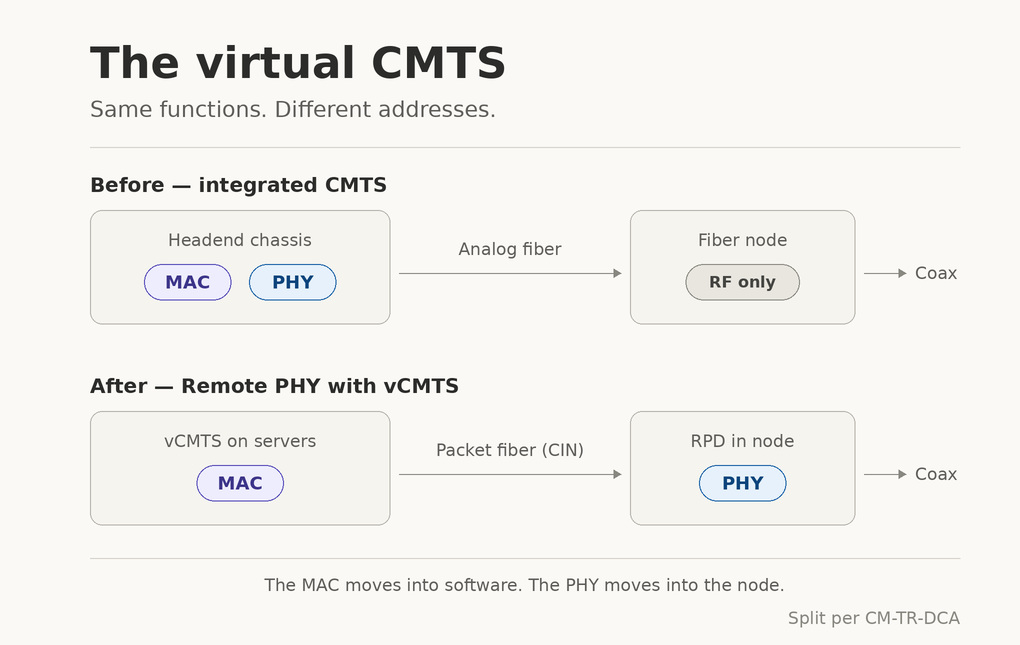
Written for the engineer who is new to cable access networks — including the one who has never seen a piece of cable plant in their life.
Last revised: September 2026
A Note Before We Start
Two promises, and one warning.
The first promise is that everything technical below is footnoted. Where I could reach primary specification text — CableLabs documents, IETF RFCs — I used it in preference to anything else. Where I am inferring, estimating, or repeating a claim I could not independently verify, I say so in the sentence itself, not in a footnote you might skip. Where sources contradict each other, I show you both and tell you how to decide.
The second promise is that I will not assume you know what a CMTS is. Part I builds it from nothing. If you already know, skim it — but read the last section of Part I anyway, because the thing that makes a CMTS unlike a router is exactly the thing that makes virtualizing it hard.
The warning is this: the vCMTS is a subject where the marketing has run considerably ahead of the engineering vocabulary. “Virtual,” “cloud-native,” “disaggregated,” and “software-defined” get used interchangeably by people who mean quite different things. A large part of becoming useful here is learning to ask which functional block moved where, and refusing to accept an answer that doesn’t name blocks. I will try to give you that vocabulary precisely.
Table of Contents
Part I — What a CMTS Is
Part II — The History
- I-CMTS: The Chassis Era
- M-CMTS and the Modular Headend Architecture
- CCAP: Convergence
- Distributed Access Architecture
- Flexible MAC Architecture
Part III — The vCMTS Itself
- What a vCMTS Actually Is
- The Interfaces That Make It Possible
- Making Software Fast Enough
- Timing: The Thing That Bites You
- Security in a Disaggregated World
- The CIN
Part IV — Practice
Part I — What a CMTS Is
1. The Problem the CMTS Solves
Start with the wire
A cable network is a tree-and-branch system. Signals originate at a headend or hub, travel over fiber to a fiber node, which converts light to radio-frequency electrical signals, and then travel over coaxial cable — through amplifiers, splitters and taps — to homes. This combination is called HFC: Hybrid Fiber/Coax.
The critical property is this: the coax is a shared medium. Every home hanging off a node shares the same physical cable. It is closer in spirit to old Ethernet-on-a-coax than to a telephone line or a fiber-to-the-home link, where each subscriber gets their own dedicated path.
Sharing has two consequences that shape everything:
- Downstream is easy. The headend transmits, everyone receives, each device picks out what’s addressed to it. This is broadcast — it’s what cable was built to do in the first place.
- Upstream is hard. If two modems transmit at the same time on the same frequency, their signals collide and both are lost. Something must decide who transmits, when, and on what frequency.
That “something” is the CMTS.
The definition
A Cable Modem Termination System is, in CableLabs’ words, “a device located at the cable television system headend or distribution hub, which provides complementary functionality to the cable modems to enable data connectivity to a wide-area network” [1].
Less formally: the CMTS is the head of the conversation. Every cable modem in a service group talks to exactly one CMTS, and the CMTS is the sole authority on who gets to speak.
The DOCSIS conversation, briefly
The protocol spoken between CMTS and cable modem is DOCSIS — Data-Over-Cable Service Interface Specifications, a family of specifications from CableLabs that “defines interoperability between cable modem termination systems and cable modems” [1].
The upstream mechanism, stripped to its essentials:
- The CMTS periodically broadcasts a MAP message (Upstream Bandwidth Allocation Map) downstream. A MAP is a schedule: it says which modem may transmit, in which minislots, on which upstream channel, starting at which DOCSIS timestamp [1][2].
- A modem with data to send transmits a REQ (bandwidth request) in a contention region or a dedicated opportunity.
- The CMTS’s upstream scheduler collects requests, applies quality-of-service policy, and writes the next MAP.
- The modem transmits in its granted slot. The burst arrives at the CMTS’s upstream receiver at the moment the schedule said it would.
That last sentence is the one to hold onto. It only works if the modem and the CMTS agree on what time it is, to within a fraction of a symbol. DOCSIS achieves this through a process called ranging, in which the CMTS measures each modem’s round-trip delay and tells it to offset its transmissions accordingly.
Everything difficult about distributing and virtualizing a CMTS traces back to this timing loop.
2. What’s Actually Inside a CMTS
CableLabs’ Distributed CCAP Architectures technical report gives the functional decomposition. A CMTS consists of [2]:
- DOCSIS PHY Layer
- Upstream Receiver
- Downstream Transmitter
- DOCSIS MAC Layer
- Upstream MAC and Scheduler
- Downstream MAC Processing
- DOCSIS QoS
- Security
- RF Output block
- L2 forwarding block
- L3 forwarding block
- IP Processing for DHCP
- SNMP agent / CLI, etc.
Learn this list. Every architecture in this document is a different answer to the question “where does each of these blocks physically live?” When someone tells you about a new access architecture, walk this list and ask where each item went. If they can’t tell you, they’re selling.
Let me expand the ones that matter most.
Downstream transmitter / RF output. Takes IP packets, frames them into DOCSIS MAC frames, encrypts them, modulates them onto radio frequencies, and pushes them out an RF port at the right power and tilt. In DOCSIS 3.1 and 4.0 this is OFDM modulation [3].
Upstream receiver. A burst receiver. Unlike a continuous receiver, it must acquire lock on a short transmission from an unknown modem, at a power level that varies modem to modem, and demodulate it correctly — then be ready for the next burst microseconds later.
Upstream scheduler and MAP builder. The brain. Real-time, hard deadlines. If the MAP is late, upstream capacity is simply lost.
Security. DOCSIS encrypts subscriber traffic using BPI+ (Baseline Privacy Interface Plus). Where BPI+ terminates turns out to be architecturally load-bearing — we’ll come back to it in §13.
L2/L3 forwarding. The CMTS is also a bridge and/or router, moving packets between the cable side and the operator’s core network. This part genuinely does resemble conventional networking gear.
3. Why a CMTS Is Not a Router
Here is the insight that will save you a lot of confusion.
A router is fundamentally stateless per packet and asynchronous. A packet arrives; you look up a destination; you send it. If you’re 50 microseconds late, nothing breaks.
A CMTS is stateful per subscriber and hard real-time in one direction. It maintains per-modem state (ranging offsets, power levels, service flows, encryption keys, modulation profiles) and it must produce upstream schedules on a deadline. Miss the deadline and you don’t drop one packet — you lose an upstream transmission opportunity for a whole service group.
There is a second, subtler point that John Chapman — the engineer who has done more than anyone to shape this architecture — made in his foundational Remote PHY paper. The DOCSIS MAC is not a clean Layer 2 entity. Analyzing the DOCSIS MAC management message set, he found that although all messages are formatted as Layer 2 frames, roughly 40% of them are IP-aware, crossing the Layer 2 / Layer 3 boundary [4].
His conclusion is worth quoting because it explains twenty years of architectural choices: “the layer 2 and layer 3 aspects of DOCSIS are quite intertwined. This is a historical fact of DOCSIS. DOCSIS was designed as an integrated system and to get the job done” [4].
That entanglement is why you cannot cleanly slice a CMTS anywhere you like. It constrains every architecture below.
Part II — The History
You cannot understand the vCMTS without the road that led to it. Each step solved a real problem and created the conditions for the next.
4. I-CMTS: The Chassis Era
The original form. An Integrated CMTS is a chassis (or a “pizza box”) in which every component needed for DOCSIS operation is integrated in one enclosure [5].
Its virtues were real: simplicity of deployment, lower cost from integration, and fewer failure points because there are no cables or interfaces between external components [5].
Its architecture was also the source of a growing problem. As operators drove service group sizes down — more nodes, fewer homes per node — they needed more RF ports. And RF ports are physical connectors. CableLabs put the constraint plainly: “The physics that constrain the size of the interface connectors limits the number of connectors that can be implemented on a single board” [2].
You cannot shrink an F-connector. So more service groups meant more line cards, more chassis, more racks, more power — in headends that were already running out of space and power [2].
Hold that thought. It is the economic engine behind everything that follows.
5. M-CMTS and the Modular Headend Architecture
The idea
The first disaggregation. Modular CMTS (M-CMTS) split the traditional CMTS into two parts: the downstream physical layer component (a DOCSIS EQAM — Edge QAM) and the IP networking plus DOCSIS MAC functions (the M-CMTS Core) [6].
The motivation was resource sharing. A video Edge QAM and a DOCSIS downstream both do the same underlying job: take packets, modulate them onto an RF carrier. If you build one universal EQAM that handles both, you can flexibly assign QAM channels to video or to data as demand shifts [2][7].
The new interfaces
Splitting a CMTS in half required inventing interfaces that had never existed outside a single chassis [6]:
- DEPI — Downstream External PHY Interface: carries DOCSIS frames from the M-CMTS Core to the EQAM.
- DTI — DOCSIS Timing Interface: provides a common frequency reference to both halves.
- ERMI — Edge Resource Management Interface: for managing QAMs on the EQAM.
- OSSI — Operations Support System Interface.
Later, video-specific specifications were added (EQAM-PMI and EQAM-VSI), and the whole suite was renamed MHA, the Modular Headend Architecture [4].
Two details worth knowing
ERMI never got used for DOCSIS. Chapman states this directly [4]. It is a useful reminder that specifications and deployments are different things, and that a published interface is not evidence anyone implemented it.
DTI was distance-limited to 200 metres on a single link [4]. Methods existed to extend this, but per Chapman “these extensions were never deployed” [4]. This mattered enormously later: it meant the timing solution that worked for two chassis in one room could not possibly work for a core in a headend and a PHY in a node ten kilometres away. Solving that required a completely different timing technology.
Chapman is careful about a distinction people routinely miss: DEPI itself is not distance-limited. In M-CMTS deployments the Core and EQAM were co-located because the upstream connections were still on the Core, and because DTI constrained the clock — but that was a property of the system, not of DEPI [4].
And UEPI, quietly
There is a nice piece of engineering history here. UEPI — the Upstream External PHY Interface — was developed at the same time as DEPI, in 2004. But there was no external market application at the time, so it was left out of the M-CMTS specifications. Then in 2007 the ASIC manufacturers adopted it, and UEPI became the internal MAC-to-PHY interface inside essentially every CMTS upstream design [4].
So by the time anyone wanted to move the upstream PHY out of the box, the interface for doing so had already been in silicon for years. That is not luck; that is what good interface design buys you.
6. CCAP: Convergence
The next step was CCAP, the Converged Cable Access Platform.
CCAP was, in CableLabs’ framing, “intended to provide a new equipment architecture option for manufacturers to achieve the Edge QAM and CMTS densities that MSOs require in order to address the costs and environmental challenges resulting from the success of narrowcast services” [7].
Functionally, “The CCAP unifies the CMTS, Switching, Routing, and QAM functions at the headend, so that all data, video, and voice functions can be handled over IP before conversion to RF or Optical signals. The CCAP eliminates the need for the combiner functionality in the headend” [2].
A piece of history that explains the name: CCAP was a CableLabs-led unification of two separate operator projects — CMAP (Converged Multiservice Access Platform), led by Comcast, and CESAR (Converged Edge Services Access Router), led by Time Warner Cable [8][9].
Notice the direction of travel. M-CMTS pulled things apart to share them. CCAP pushed them back together to densify them. This oscillation between integration and disaggregation is not confusion — it is engineering responding to which constraint binds hardest at the time. Right now the binding constraint is space, power and software velocity, which is why we are disaggregating again.
7. Distributed Access Architecture
The problem CCAP couldn’t solve
CCAP densified the headend, but it could not repeal physics. More service groups still meant more RF ports, and the connectors still had a minimum size [2].
Meanwhile a second pressure was building: the analog optical link between headend and node. Analog (linear) optics demand a high signal-to-noise ratio, require relatively high optical powers, contribute noise that limits achievable SNR, and need periodic recalibration [4]. As DOCSIS 3.1 arrived with modulation orders up to 4096-QAM, that optical noise floor became a direct constraint on how much data you could push [2].
The answer to both problems is the same: put the modulation at the node, and make the fiber digital.
Digital fiber
CableLabs lists the benefits of moving the PHY to the node: reduced attenuation and accumulated impairments, lower bit error rates, improved SNR, and consequently the ability to use higher modulation orders on DOCSIS 3.1 channels [2]. Digital optics also allow far denser wavelength packing — typical analog spacing is 100 GHz allowing up to 40 wavelengths per fiber, whereas digital spacing of 25 GHz or less leaves room for 160 or more [2].
Chapman adds a specific and striking claim: because the optical noise contribution to SNR is eliminated, a remote QAM modulator placed after the fiber link can run at higher modulation orders than a centralized one — “depending upon the HFC plant architecture, the difference can be as high as two orders of modulation” [4].
The three approaches
CableLabs defines the basic idea of Distributed CCAP Architecture (DCA) as distributing “some or all of the functionality of the CMTS/CCAP down to a remote location, like the Fiber Node” [2]. Three approaches emerged [2]:
| Approach | Where the split is | What lives in the node |
|---|---|---|
| Remote PHY (R-PHY) | Between MAC and PHY | PHY only |
| Remote MAC-PHY (R-MACPHY) | Above the MAC | MAC and PHY |
| Split-MAC (C-DOCSIS II) | Inside the MAC | Part of the MAC, plus PHY |
Remote PHY is the one that matters most for understanding vCMTS. In an R-PHY system the integrated CCAP is separated into a CCAP Core and a Remote PHY Device (RPD). The CCAP Core contains both a CMTS Core for DOCSIS and an EQAM Core for video [2].
The CMTS Core “contains the DOCSIS MAC and the upper layer DOCSIS protocols. This includes all signaling functions, downstream and upstream bandwidth scheduling, and DOCSIS framing” [2]. The RPD “contains mainly PHY related circuitry, such as downstream QAM modulators, upstream QAM demodulators, together with pseudowire logic to connect to the CCAP Core” [2].
Remote PHY is also known as MHAv2 — Modular Headend Architecture version 2 — because it genuinely builds on the original MHA [2][4]. The lineage is direct: DEPI and UEPI, invented for M-CMTS, became R-DEPI and R-UEPI for Remote PHY, now running over an arbitrary IP network instead of a cable across the room.
Remote MAC-PHY moves both MAC and PHY to the node. The link from headend to node becomes essentially a Layer 2 Ethernet connection [2]. There is an important, easily-missed consequence: because MAC and PHY are co-located in the RMD, “there is no hard requirement for distributed synchronization and timing for DOCSIS data services” [2]. R-MACPHY dodges the timing problem that R-PHY must solve.
There is a second, equally important consequence in the other direction, which I’ll cover in §13.
The strategic point
One sentence from the DCA technical report deserves to be framed and hung on a wall, because it is the hinge between Part II and Part III of this document:
“Virtual implementations still require a hardware device to provide the physical layer transmission functions such as RF modulation so that some form of DCA is a prerequisite for NFV. Distributed CCAP Architectures are an initial step towards virtualization.” [2]
You cannot have a vCMTS without DAA. Software on a general-purpose server cannot produce a 1.2 GHz RF signal. Something has to do the modulation, and once you’ve moved that something to the node, what remains is — by construction — a pile of packet processing and control logic. Which is to say: software.
8. Flexible MAC Architecture
The last piece of standards history.
By 2017, operators moving from integrated CCAP to disaggregated cores plus RPDs were discovering an operational problem. DAA was unbundling CMTS, MAC and PHY functions in several different ways, across physical chassis and virtual implementations, and the back-office systems had no consistent way to manage the resulting zoo [10].
FMA — Flexible MAC Architecture — is CableLabs’ answer. FMA specification work started in late 2017, led on the operator side by Jeff Finkelstein of Cox Communications [11][12], and the first library of specifications was released in September 2020 [11][13].
CableLabs’ own definition: FMA is “the distributed CMTS/CCAP architecture where the DOCSIS MAC and PHY layer processing of a CMTS are disaggregated and moved deeper into the access network” [14]. More concretely, “FMA defines the standardization of the complete disaggregation of the CCAP management, control and data planes” [13].
The specification family is [14]:
| Designation | Title |
|---|---|
| CM-SP-FMA-SYS | Flexible MAC Architecture System Specification |
| CM-SP-FMA-MMI | FMA MAC Manager Interface Specification |
| CM-SP-FMA-PAI | FMA PacketCable Aggregator Interface Specification |
| CM-SP-FMA-OSSI | FMA Operations Support System Interface Specification |
Why FMA matters to you
Two reasons.
First, it gives us the vocabulary. FMA introduces the term MAC-NE (MAC Network Element) for whatever box or process is doing the MAC, and enumerates the forms it can take: RMD (Remote MACPHY Device), RMC (Remote MAC Core), pCore (physical core), and vCore (virtual core) [14].
That last one is the point. “vCore” is the standards-body term for the DOCSIS core function implemented in software. When a vendor says vCMTS and you want to know what they actually mean, ask whether they mean a vCore in the FMA sense.
Second, it standardizes management across all of them. The MAC Manager Interface (MMI) “sets itself apart from hardware abstraction interfaces in that there will not be different interfaces defined for each vendor’s MAC Network element, such as RMD, RMC, pCore, and vCore. This interface operates at a higher layer so that the same interface may be used regardless of MAC Manager and MAC-NE supplier” [14].
The MAC Manager is an aggregation point whose job is “to make the many appear as one to the back-office systems” [14]. That phrase captures the central operational problem of DAA in seven words.
MMI is built on RESTCONF/YANG over HTTPS [14] — modern, model-driven network management, not SNMP. The MAC-NE hosts the RESTCONF server; the MAC Manager is the client [14]. If you know REST APIs and YANG models, you already know most of how a modern cable access network is managed. That is a significant change from the SNMP-and-CLI world of the chassis era.
Part III — The vCMTS Itself
9. What a vCMTS Actually Is
The definition
A virtual CMTS is the CMTS Core (or CCAP Core) function — everything above the PHY — implemented as software running on commercial off-the-shelf servers, rather than as firmware on purpose-built hardware.
A patent filing puts the standards relationship precisely: “As defined by the CableLabs Remote PHY standard, the DOCSIS physical layer is separated from all the upper layers, via the standards-based protocols [R-DEPI], [R-UEPI], and [GCP]. When referring to the vCMTS component in the context of virtualization, the CMTS Core functionality (as defined in the CableLabs Remote PHY standards) is implemented as a virtual application” [15].
An industry description adds the operational shape: the vCMTS “runs on a cluster of Common Off the Shelf (COTS) servers, such as 1-RU Intel x86, which are not bound to a single chassis,” should perform all CMTS functions including common control and IP forwarding, and “is scaled simply by spinning up new vCMTS containers on available COTS servers” [16].
What a vCMTS is not
Four confusions worth clearing immediately.
It is not R-MACPHY. These are alternatives, not synonyms. In R-PHY plus vCMTS, the MAC is in software in the headend. In R-MACPHY, the MAC is in hardware in the node. Both are DAA. They are different answers.
It is not necessarily “in the cloud.” In practice vCMTS runs on operator-owned servers in headends and hubs, close to the plant, for latency and timing reasons discussed in §12 and §14. Comcast, for instance, describes running its vCMTS on a company-developed edge compute cluster [17]. “Cloud-native” here means the software is built like cloud software — containerized, orchestrated, horizontally scaled — not that it runs in someone else’s data centre.
It is not necessarily a virtual machine. Most implementations are containerized rather than VM-based [15][18]. “Virtual” in vCMTS means “implemented in software on general-purpose compute,” not “running under a hypervisor.”
It does not eliminate hardware. It relocates it. You still have RPDs in the field, servers in the hub, and a switching fabric between them. What you have removed is purpose-built, single-function, long-lived hardware from the headend.
Why bother
The honest list, with the evidence:
Space and power. This is the biggest and best-evidenced benefit. Comcast has reported that its vCMTS approach represents roughly a 20:1 reduction in the number of cabinets required to deliver high-speed data compared to legacy purpose-built CMTS hardware [18]. In generational terms, Comcast reported a third-generation vCMTS enabling one rack to serve about 100,000 households passed, up from 60,000 for the second generation — versus legacy analog CMTSs requiring about 20 racks to serve 60,000 homes passed [19].
Capacity growth by software and silicon refresh. The same Comcast report attributes the generational scaling to “just following Moore’s Law” [19]. When your CMTS is software, a server refresh is a capacity upgrade.
Feature velocity. Upgrading software rather than replacing physical equipment [17]. This is the argument operators make most often and the one hardest to quantify.
Smaller failure domains. CableLabs anticipated this: virtualization high-availability strategies are “typically based on the reduction of failure group size and horizontal scaling, as multiple small components replace a single large platform (e.g., a virtual CMTS per serving group rather than an integrated platform serving many)” [2].
Convergence across access technologies. Because the vCMTS is software doing packet processing, the same platform can be extended to other access types. Comcast has stated it uses the same vCMTS platform to support FTTP deployments via remote OLTs and a virtual BNG [20][21].
I’ll give the energy numbers in §16, because they need context.
10. The Interfaces That Make It Possible
This is the technical heart. If you learn one section properly, make it this one.
Pseudowires
Everything in Remote PHY rests on the pseudowire. Chapman’s definition: “A Pseudowire is an emulation of a point-to-point connection over a packet-switching network (PSN)… A Pseudowire allows an IP network to carry a service without that service having to know the details of the IP network” [4].
The formal architecture is IETF RFC 3985, Pseudo Wire Emulation Edge-to-Edge (PWE3) Architecture, March 2005 [22].
(A small note on care with sources. Chapman’s paper cites this as “RFC 3955” [4]. RFC 3985 is the PWE3 architecture document [22]. It is a typo in an otherwise excellent paper by the field’s leading architect. I mention it not to score a point but because you will inherit citations from other engineers for your entire career, and the habit of clicking through to check them is one of the cheapest ways to be reliably correct.)
Remote PHY chose L2TPv3 — Layer 2 Tunneling Protocol version 3 — as its pseudowire protocol, for four stated reasons: the underlying network is IP, there is a reliable session setup protocol, there is support for multiple pseudowires per session, and the specification is publicly available for implementation [4].
One implementation detail worth knowing, because it shows up the first time you open a packet capture: the 32-bit L2TPv3 session ID occupies the same position in the packet that UDP source and destination ports would. This is deliberate — it lets existing packet filters that can match on UDP ports match on L2TPv3 session ID instead. A session ID of all zeros marks a control-plane packet; non-zero marks data plane [4].
R-DEPI (downstream)
R-DEPI is the downstream interface between CCAP Core and RPD. It is “an IP pseudowire between the MAC and PHY that contains both a data path for DOCSIS frames, video packets, and OOB packets, as well as a control path for setting up, maintaining, and tearing down sessions” [2].
Typical control messages establish a control connection between Core and RPD, then set up multiple data sessions — one for each downstream and upstream QAM or OFDM channel. Each session can be marked with different DSCPs and support different encapsulations [2].
There are two data encapsulation modes [2][4]:
- MPT (MPEG Transport) mode transports multiple 188-byte MPEG-TS packets in the L2TPv3 payload. The encapsulation of DOCSIS frames into MPEG-TS packets happens in the CCAP Core.
- PSP (Packet Streaming Protocol) mode transports DOCSIS frames directly in the L2TPv3 payload. Encapsulation into MPEG-TS happens in the RPD. PSP allows DOCSIS frames to be both concatenated (for network efficiency) and fragmented (in case tunneled packets exceed network MTU).
And the rule for which is used where: “MPT mode is generally used for single carrier QAM systems such as DOCSIS 3.0 and video, while PSP mode is used for downstream OFDM channels and for the DOCSIS upstream” [2].
If you take away one fact about DEPI modes, take that one. It comes up constantly.
R-UEPI (upstream)
R-UEPI carries DOCSIS frames that the RPD’s upstream PHY has received and demodulated, back to the CCAP Core for processing. It uses the same L2TPv3 control plane structure as R-DEPI with different encapsulations [2][4].
Here is a genuinely elegant detail. The RPD does essentially no upstream DOCSIS processing — with one exception: “the RPD will extract the bandwidth request frames from the DOCSIS stream and send them in a separate pseudowire so that bandwidth request frames can be given a higher priority than data frames” [2].
Think about why. Bandwidth requests feed the scheduler. If a REQ is delayed behind a burst of bulk upstream data crossing the network, the scheduler makes a decision on stale information and upstream latency suffers. So the RPD sorts them at the source and they get their own priority-marked tunnel.
Chapman’s original UEPI design defines five pseudowires: a data pseudowire, and separate ones for MAP, RNG-REQ and REQ messages so they can receive higher QoS treatment, plus a spectrum-management pseudowire [4]. He notes candidly that in practice “this performance mode is not needed if there is sufficient network bandwidth on the UEPI interface such that congestion never occurs” [4].
That is a good engineer talking. The mechanism exists for when the network is imperfect; the better answer is usually to make the network not congested.
GCP (control)
The RPD is a slave device controlled by the CCAP Core using GCP — the Generic Control Plane protocol [2].
The model is simple: the GCP master (CCAP Core) initiates reads and writes to the GCP slave (RPD); the slave can initiate a notify message to get the master’s attention. GCP also has a peer-to-peer mode which is “really just two independent master-slave nodes, in opposite directions, on the same port number” [2].
In R-PHY, GCP uses TCP/IP as its transport, to provide a reliable connection independent of the interconnect network [2].
Zero-touch provisioning
A design goal worth knowing: “It was a design goal that the RPD should operate ‘out of the box’ with no pre configuration required. To achieve this it uses DHCP to obtain its IP address and the address of a controlling CCAP core. It then establishes a connection to the core and retrieves configuration information via GCP. Thus, operator configuration of the RPD is performed indirectly via configuration of the CCAP-Core” [2].
This is what lets a field technician hang a node without touching a CLI — which, as we’ll see in §15, is the entire operational premise of DAA.
11. Making Software Fast Enough
Now the question every software engineer asks: can general-purpose CPUs really do this?
The answer is yes, but not by accident, and not with an ordinary networking stack.
Why the kernel isn’t enough
A DOCSIS downstream service group at DOCSIS 3.1 rates involves gigabits per second of traffic that must be classified, queued, shaped, framed, encrypted, and encapsulated — per subscriber, per service flow. Standard Linux kernel networking, with its interrupts, context switches, and per-packet socket buffer allocations, cannot sustain this at reasonable core counts.
DPDK
The standard answer is DPDK — the Data Plane Development Kit. Intel’s vCMTS reference work describes its application as “a DOCSIS media access control (MAC) data plane pipeline based on DOCSIS 3.1 specifications and the Data Plane Development Kit (DPDK) packet processing framework,” whose purpose is “to provide a tool for characterization of vCMTS data plane packet processing performance and power-consumption on Intel Xeon platforms” [23].
DPDK’s core techniques — poll-mode drivers instead of interrupts, hugepages to reduce TLB pressure, cores pinned to specific threads, zero-copy buffer management — are general to high-performance packet processing, not specific to cable. If you have worked on any modern software router, virtual firewall or 5G UPF, you have met them.
The pipeline
Intel’s reference design divides the downstream into upper MAC and lower MAC stages, executed as separate software threads pinned to hyper-thread siblings on a single core [24][23].
Roughly, upper MAC handles the per-subscriber, per-service-flow work — classification, policing, queueing, scheduling. Lower MAC handles the per-frame work — DOCSIS framing, encryption, CRC, and encapsulation into DEPI. Splitting them lets each be optimized and scaled independently.
Hardware acceleration that isn’t a chassis
The crucial insight is that “software CMTS” does not mean “no hardware acceleration.” It means the acceleration lives in the general-purpose CPU and its peripherals rather than in a bespoke ASIC. The published Intel work cites [24][25]:
- Intel AES-NI — instruction-level acceleration for AES, used for DOCSIS BPI+ encryption and decryption of all frames [25]
- Intel AVX-512 — wide vector instructions
- Intel QuickAssist Technology (QAT) — an offload engine; later releases added combined cipher-and-CRC offload to QAT 2.0 [26]
This is why the vCMTS became viable when it did. It is not that someone finally wrote clever enough code; it is that commodity server silicon acquired the specific primitives DOCSIS needs.
Orchestration and power
Modern vCMTS implementations are containerized and orchestrated. Intel’s reference platform supports deployment on both a bare-metal reference architecture and Red Hat OpenShift, and includes Grafana dashboards for monitoring platform and dataplane statistics, plus a Power Manager that reduces CPU core power consumption during quiet network periods [26][25].
That power manager deserves a moment. A poll-mode driver spins a CPU core at 100% whether traffic is flowing or not — which is terrible for a device that must sit in a hub for a decade. Later Intel releases added power-optimized C-states for DPDK dataplane cores using the WAITPKG instruction set via the DPDK Power Management API [26]. The energy story in §16 depends on work like this.
An honest caution on performance numbers
You will see vCMTS throughput and density figures from vendors, from silicon suppliers, and from operators. Treat all of them as conditional.
Intel’s own framing is careful — the reference dataplane exists to “establish an empirical performance data baseline that can be used to estimate the capability of a vCMTS platform” [24]. That is a much more modest claim than a marketing number.
When you are given a density figure, ask: which CPU generation and SKU? How many cores allocated to the dataplane versus control? What packet size distribution — RFC 2544 style fixed sizes, or a realistic mix? Is encryption enabled on all frames? Is it upstream, downstream, or aggregate? Downstream-only numbers with large packets and crypto offloaded will be several times better than a realistic mixed workload. Neither number is dishonest; they answer different questions.
12. Timing: The Thing That Bites You
If you remember §1, you know why this section exists.
The problem restated
In Remote PHY, the CMTS Core and the RPD are in different chassis and potentially different physical locations. But the downstream PHY and upstream PHY are together on the RPD under a common clock, while the upstream scheduler and MAP builder are part of the MAC, located at the CMTS Core [2].
CableLabs states the requirement exactly: “The DOCSIS time described by the MAP needs to allow correct burst reception at the RPD. Therefore the CMTS Core and the RPD need to have a common knowledge of the DOCSIS time” [2].
The Core writes a schedule. The RPD must receive bursts according to that schedule. If their clocks disagree, bursts land in the wrong slots and the upstream degrades or fails.
R-DTI
DTI’s 200-metre limit [4] made it useless here. The replacement is R-DTI — the Remote DOCSIS Timing Interface — which “leverages IEEE1588v2 Precision Time Protocol (PTP) to replace the DTI infrastructure used for M-CMTS” [2].
IEEE 1588v2 is “a hierarchical, master-slave architecture for clock distribution using a packet-based two-way message exchange protocol for synchronizing clocks to enable accurate time distribution over a network. Timing signals from a Grand Master (GM) clock are propagated through the network to the slaves. The protocol provides for timing adjustments to compensate for transmission time” [2].
R-DTI supports three modes [2]:
- The RPD is clock master, Core is slave
- The CCAP Core is clock master, RPD is slave
- Both RPD and Core are slaves to an external clock master
In practice the third is the common deployment: an external Grandmaster, typically GPS-disciplined, with both ends slaved to it.
Why this is harder than it looks
PTP measures network delay by exchanging timestamped messages and assuming the path is symmetric. Both assumptions can fail.
CableLabs warns: “A moderately or heavily loaded network can have a significant impact on the ability of the PTP slave to synchronize to the PTP master, both in terms of settling times and offset ppm tracking accuracy” [2].
Mitigations, per the same source [2]:
- Managed network elements that prioritize traffic and deliver PTP messages with low latency
- Intervening network elements acting as IEEE 1588 transparent or boundary clocks, compensating timestamps for network jitter
- Synchronous Ethernet (SyncE) capable devices to allow quick initial settling
In vendor practice, PTP profiles matter. Cisco documents G.8275.1 (phase/time synchronization with full timing support from the network) and G.8275.2 (partial timing support), and recommends G.8275.2 over the older Telecom-2008 profile for R-PHY as more resilient to failures [27].
The lesson
Here is the thing I most want a junior engineer to internalize about DAA and vCMTS.
The moment you split MAC from PHY across a packet network, timing stops being a solved problem and becomes a design problem. Every switch in the path is now part of your clock distribution system. A network engineer who reconfigures a switch without knowing it carries PTP can break the upstream of an entire region, and the symptom will look like an RF problem.
Note the asymmetry this creates between architectures: R-MACPHY has “no hard requirement for distributed synchronization and timing for DOCSIS data services” because MAC and PHY are co-located in the RMD [2]. This is a genuine architectural advantage of R-MACPHY, and it is the counterweight to the advantages R-PHY has elsewhere.
13. Security in a Disaggregated World
The new exposure
CableLabs is blunt about what DAA costs you: “The R-PHY architecture requires MSOs to deploy a large number of IP networking devices (the RPDs) into inherently unsecure portions of the network, such as pole mounted nodes and remote cabinets. This extension of IP deeper into the plant exposes the network to a number of security threats such as unauthorized network access, loss of customer privacy, theft of service and denial of Service attacks on the network itself” [2].
The FMA specification says the same about its components: “at least some of the components are expected to be deployed in insecure locations, whether that be on the pole, in a pedestal, or inside of a curb vault” [14].
Chapman raised exactly this concern years earlier as an argument against putting a whole CMTS in a node: the CMTS manages BPI, configuration file transfer, and has a CLI input, so “If the remote node was broken into, the system could be hacked much easier than if the CMTS was located in a secure hub site” [4].
How R-PHY responds
The layered answer [2]:
Network access. On boot, the RPD authenticates to the network using 802.1x port-based access control. Identification uses digital certificate credentials from the CableLabs PKI, securely installed during RPD manufacture. The switch may additionally require MACsec (link-layer encryption) between switch and RPD.
Core-to-RPD. After gaining network access, the CCAP Core and RPD perform mutual authentication based on CableLabs PKI certificates. Control plane security uses IPsec and may be authenticated, encrypted, or left in the clear depending on Core configuration.
Software download. RPD code is signed with a CableLabs PKI certificate and validated by the RPD — broadly, “the RPD assumes the functions of a DOCSIS cable modem” for secure software download purposes.
The BPI+ termination point — an important architectural difference
This is subtle and it matters.
In R-PHY, “DOCSIS BPI+ processing occurs in the CCAP Core. Thus the data plane traffic is encrypted from the core to the cable modem and no further protection is needed” [2].
Read that again. Subscriber traffic is already encrypted when it enters the DEPI tunnel, because the encryption endpoint is the Core and the other endpoint is the modem. The RPD is inside the encrypted span. You get data-plane confidentiality across the CIN for free.
In R-MACPHY, the MAC moved to the node, so “The BPI+ protection of user traffic occurs only between the CM and remote device (RMD)… Therefore, the data link between the RMD and CCAP Core will need to be secured to protect user traffic” [2]. IPsec is used to protect user data and Layer 3 management traffic; MACsec can protect Layer 2 management traffic [2].
So: R-MACPHY escapes the timing problem (§12) but inherits a data-plane encryption problem. R-PHY has the opposite trade. There is no free architecture. Every split you choose gives you one set of problems in exchange for another, and a good architect can name both sides of the trade for whichever one they chose.
FMA management security
For the management plane, FMA requires X.509 certificates for interface authentication, TLS handshake for mutual authentication and cipher negotiation, and encryption between authenticated components [14].
Concretely, MMI requires HTTP/1.1 over TLS 1.2 at minimum, with TLS 1.3 optional, on TCP port 443, and the MAC-NE must reject any HTTP request not secured with TLS [14].
14. The CIN
The packet network between the core and the remote devices has a name: the Converged Interconnect Network (CIN) [2].
You will spend a surprising amount of your time on it. CableLabs specifies what it must provide [2]:
Throughput. Sufficient to support the advertised service level. The simplest approach is for CIN bandwidth to exceed HFC bandwidth, which is easily achieved with point-to-point 10G Ethernet. If the CIN uses shared media such as PON, oversubscription may reduce cost but must be based on traffic engineering models.
Packet loss. “The CIN network should be engineered such that congestion is avoided.” Note the reasoning: even short congestion periods cause drops, because “modern switches have very small buffers relative to their switching capacity” [2].
Latency and jitter. Transmission delay in fiber is approximately 500 µs per 100 km; delay and jitter in modern switches are minimal when not oversubscribed — under 2 µs for a 1518-byte packet in a 10G switch [2]. The report concludes that moving the Core to a more distant location affects the DOCSIS request-grant scheduling loop, “but even this has minimal impact below 500km and can be easily mitigated well beyond this” [2].
That 500 km figure is worth carrying. It means CIN geography is a real constraint but a generous one — you are not forced to put the core in the same building.
Timing. The CIN must be able to provide timing to remote devices using PTP [2].
Redundancy. Redundant paths with fast failover, or multiple paths for load balancing — but “the impact of different path options on jitter must be considered” [2].
Multicast. The CIN should support IP multicast for efficient broadcast and multicast video [2].
The summary sentence: “the CIN should be a high-speed managed network operated at less than full capacity to minimize packet loss, latency and jitter” [2].
That phrase — operated at less than full capacity — cuts against every instinct a network engineer has about utilization efficiency. In the CIN, headroom is not waste. It is what buys you deterministic timing.
Part IV — Practice
15. What Actually Changes Operationally
The division of labour
CableLabs identified the human problem early. DAA “shifts equipment, traditionally managed and serviced in the hub, to locations on the plant traditionally serviced by field technicians that are accustomed to working with outside plant equipment” [2].
The recommended split [2]:
Field technicians focus on installation, replacement and basic troubleshooting of plant electronics — mounting, cabling, powering, network connectivity, RF adjustment, identifying and replacing failed components, hardware upgrades. Explicitly, they should be avoiding software configuration or troubleshooting in the field.
Headend/hub technicians focus on software configuration and troubleshooting using remote management tools — initial configuration and provisioning, fault troubleshooting including low-level direct access to remote devices, software upgrades.
This is why zero-touch RPD provisioning (§10) is not a convenience feature. It is the mechanism that makes the labour split possible.
Visibility improves dramatically
An honest comparison from the same source: “An analog fiber node provides almost no information about the health or state of the node.” R-PHY and R-MACPHY “provide much more detailed information on both the node and the communications to and from the node, and allows some interactive access to additional information when needed” [2].
But note the caveat, which has aged well: “While the quality and quantity of information about the node is dramatically increased, much of it is not organized to simplify remote fault diagnosis. Additional work is needed to maximize the value of this information” [2].
Ten years on, that is still where much of the operational effort goes. Collecting telemetry is easy. Making it actionable is the job.
Telemetry replaces polling
The management model shifts. FMA’s northbound OSS interface still implements SNMP, traps, syslog and IPDR, with NETCONF optional for configuration [14] — but the MAC-NE northbound interface adds streaming telemetry [14].
Industry commentary on operating vCMTS notes that both vCMTS and legacy CMTS use CLI and SNMP with similar limitations, but vCMTS platforms add streaming telemetry [28]. If your background is in modern observability — time-series databases, push-based metrics, dashboards — that skill transfers directly.
More devices to manage
The counterweight. “The nature of distributed CCAP architectures will include a substantial increase in the number of physical devices being managed to serve the same number of subscribers, even without decreases in number of subscribers per service group. OSS interface abstractions provide a way to more effectively manage this larger quantity of devices” [2].
This is precisely the problem the FMA MAC Manager exists to solve — making the many appear as one [14].
Deployment and scaling shape
A practical description: deploying a vCMTS is similar to deploying a legacy CMTS, only it typically involves installing servers and a switch rather than a larger chassis; and scaling, where legacy CMTS meant more RF cards and chassis, now means more servers [28].
High availability changes character
Chassis CMTS redundancy was vertical — redundant supervisors, redundant line cards, redundant power in one box. Virtualized HA is horizontal, “based on the reduction of failure group size and horizontal scaling” [2].
The practical effect is a different risk profile rather than uniformly better reliability. CableLabs notes that “the number of subscribers impacted by the failure of a given component can vary greatly: failure of a remote device may only impact a small service group, while failure of a critical headend component could impact a number of users greater than what would be seen with the failure of a line card in a CCAP” [2].
Small failures get smaller. Certain large failures can get larger. Design accordingly.
Powering
One thing that does not change much: RPDs and RMDs will in most cases draw power from the coaxial network, using the same 60 VAC or 90 VAC line-frequency sources with or without battery standby that conventional HFC nodes use. Power consumption may change and may require modifying the capacity — but not the character — of the power source [2].
16. Deployment Reality
This section ages fastest. Verify before quoting. Current as of September 2026.
Comcast
The most-documented deployment, and the reference case.
Comcast states it began its distributed access architecture and virtualization journey in 2018 [17]. Reported milestones:
- October 2023: more than 120,000 remote PHY nodes deployed, paired with more than 1,000 “PPODs” — the physical hardware running the vCMTS compute [19].
- 2024: “more than half of customer modems on our network are connected through our vCMTS platform,” with an expectation of nearly two-thirds by the end of that year [17].
- Generational density: third-generation vCMTS at about 100,000 households passed per rack, versus 60,000 for generation two, versus about 20 racks per 60,000 homes passed for legacy analog CMTS [19].
- 2026: roughly 225,000 digital nodes deployed, with “tens of thousands” DOCSIS 4.0-capable, and multi-gigabit service reaching “millions” of homes [29][30].
The vCMTS also underpins Comcast’s fiber strategy: the same platform supports FTTP via remote OLTs and a virtual BNG [20][21].
The energy numbers, with context
Comcast reports reducing its electricity per consumed byte metric by 55% between 2019 and 2025 — from 18.4 kWh/TB to 8.2 kWh/TB — while data traffic on the network grew 89%, and total electricity consumption declined 15% over the same period [31].
Read this carefully, because it is easy to over-claim. Comcast describes the shift from chassis-based CMTS to vCMTS as “a key pillar” of these gains [31], but the reported figures cover a whole-network programme that also includes DAA, new nodes, smart amplifiers, and a decade of general equipment efficiency improvement. The vCMTS contributed; the number is not attributable to the vCMTS alone. Anyone who tells you “vCMTS cut energy use 55%” is misreading the source.
The vendor landscape
The figures below are dated snapshots from the reporting I could verify, not current numbers. Customer and modem counts in particular grow quarter to quarter — check current filings before quoting any of them.
- Harmonic is the market leader. Its platform, originally CableOS, was rebranded cOS in 2023 [32]. As of its Q2 2023 reporting it had 94 operator customers with deployments covering roughly 21 million cable modems [32][33]. Comcast is its largest customer; Charter signed on for a network evolution plan calling for vCMTS to support about 85% of its HFC footprint [34][35].
- Vecima entered the market in March 2024 with its containerized Entra vCMTS [36][37], and announced Cox Communications as its first vCMTS customer in April 2025, with Cox expected to transition over about five years, migrating away from Cisco’s cBR-8 [38].
- CommScope re-energized its vCMTS effort and acquired Casa Systems’ cable assets [38].
- Cisco developed vCMTS technology but has put that work on indefinite hold [34][38].
On market size, Dell’Oro Group analyst Jeff Heynen estimated Harmonic held roughly 98% of the vCMTS market at the end of 2023, and forecast the market growing from about $162 million globally in 2023 to around $366 million in 2028 [37]. Treat the forecast as a forecast.
One more data point on direction of travel, which I pass on with its methodology attached: a Dell’Oro survey of 50 cable operators worldwide, conducted in Q1 2022, reported that 100% of respondents had either deployed or planned to deploy a vCMTS architecture within 24 months [34]. A 100% result on a 50-respondent survey tells you about intent and about who answers surveys; it does not tell you about deployment timelines, which have generally been slower than intent.
17. Traps and Misconceptions
“vCMTS and R-MACPHY are the same thing.” No. R-PHY plus a vCMTS puts the MAC in software in the headend. R-MACPHY puts the MAC in hardware in the node. Both are DAA; they are alternatives.
“vCMTS means the CMTS runs in the cloud.” In practice it runs on operator servers in headends and hubs. Comcast runs its vCMTS on a purpose-built edge compute cluster [17]. Timing and CIN engineering constrain how far away you can put it (§12, §14).
“Virtual means no hardware.” You still need RPDs, servers and a switching fabric. DAA is a prerequisite for virtualization, not an alternative to it [2].
“You can virtualize the PHY too.” Not with general-purpose compute producing RF. Something must modulate. That something is the RPD.
“DEPI is distance-limited.” It is not; DTI was. Chapman is explicit that the co-location of M-CMTS Core and EQAM was a system property, not a DEPI property [4].
“Remote PHY was invented for vCMTS.” Chapman states he invented Remote PHY in 2001 and brought it to standards in 2004 as M-CMTS [4] — years before anyone was seriously discussing virtualizing a CMTS. Virtualization became possible because R-PHY existed, not the other way round.
“Timing is handled by the spec, so I don’t need to think about it.” R-DTI specifies the protocol. It does not engineer your CIN. Network loading materially degrades PTP synchronization [2].
“vCMTS is inherently more reliable.” It has different failure characteristics. Small failure domains shrink; some headend failure domains grow [2].
“A vendor throughput number tells me capacity.” Not without the CPU generation, core allocation, packet size mix, direction, and whether encryption is enabled (§11).
“The 55% energy reduction was the vCMTS.” It was a whole-network programme over six years, of which vCMTS was one key pillar [31].
“MPT and PSP are interchangeable DEPI modes.” MPT is generally for SC-QAM and video; PSP is for downstream OFDM and the DOCSIS upstream [2].
18. Glossary
Definitions marked † are quoted or closely paraphrased from CableLabs specifications or technical reports [2][14].
| Term | Meaning |
|---|---|
| BPI+ | Baseline Privacy Interface Plus — DOCSIS link encryption and authentication |
| CCAP | Converged Cable Access Platform — unifies CMTS, switching, routing and QAM functions at the headend † |
| CCAP Core | A CCAP device that uses Remote PHY protocols to interconnect to an RPD; contains a CMTS Core and an EQAM Core † |
| CIN | Converged Interconnect Network — the packet network between core and remote devices † |
| CM / CMTS | Cable Modem / Cable Modem Termination System † |
| DAA / DCA | Distributed Access Architecture / Distributed CCAP Architecture † |
| DEPI / R-DEPI | (Remote) Downstream External PHY Interface † |
| DOCSIS | Data-Over-Cable Service Interface Specifications † |
| DPDK | Data Plane Development Kit — userspace packet processing framework |
| DTI / R-DTI | (Remote) DOCSIS Timing Interface † |
| EQAM | Edge QAM modulator † |
| FMA | Flexible MAC Architecture — the distributed CMTS/CCAP architecture where DOCSIS MAC and PHY processing are disaggregated and moved deeper into the access network † |
| GCP | Generic Control Plane — master/slave control protocol between CCAP Core and RPD † |
| HFC | Hybrid Fiber/Coax † |
| I-CMTS | Integrated CMTS — all components in one chassis † |
| L2TPv3 | Layer 2 Tunneling Protocol version 3 — the pseudowire protocol used by DEPI/UEPI † |
| MAC Manager | FMA entity serving as single point of contact between back-office systems and FMA access network elements † |
| MAC-NE | MAC Network Element — generic FMA term covering RMD, RMC, pCore and vCore † |
| MAP | Upstream Bandwidth Allocation Map — the upstream schedule † |
| M-CMTS | Modular CMTS — CMTS split into M-CMTS Core and EQAM † |
| MHA / MHAv2 | Modular Headend Architecture (version 2); MHAv2 is Remote PHY † |
| MMI | MAC Manager Interface — RESTCONF/YANG southbound interface in FMA † |
| MPT / PSP | DEPI encapsulation modes: MPEG Transport / Packet Streaming Protocol † |
| pCore / vCore | Physical core / virtual core — FMA terms for the DOCSIS core function † |
| PTP | Precision Time Protocol, IEEE 1588 † |
| REQ | DOCSIS upstream bandwidth request † |
| RMD / RMC | Remote MACPHY Device / Remote MAC Core † |
| RPD | Remote PHY Device — converts digital Ethernet transport to analog RF transport † |
| SyncE | Synchronous Ethernet † |
| UEPI / R-UEPI | (Remote) Upstream External PHY Interface † |
| vCMTS | Virtual CMTS — CMTS Core functionality implemented as a software application on COTS compute |
19. References
Primary specifications and technical reports
[1] Cable Television Laboratories, Inc., DOCSIS 4.0 Physical Layer Specification, CM-SP-PHYv4.0-I03-201202, 2 December 2020. (Terms and definitions; CMTS and DOCSIS definitions; MAP and upstream terminology.) — https://account.cablelabs.com/server/alfresco/553828be-22fe-4566-9d9d-85b79fb94a7e
[2] Cable Television Laboratories, Inc., Distributed CCAP Architectures Overview Technical Report, CM-TR-DCA-V01-150908, 8 September 2015. The single most useful document for this subject. (CMTS functional decomposition §5.1; MHA §5.3; CCAP §5.4; three DCA approaches §7; Remote PHY §8 including R-DEPI, R-UEPI, GCP, security, timing; Remote MAC-PHY §9; operational considerations §11; CIN requirements §11.9; SDN/NFV §11.10.) — https://account.cablelabs.com/server/alfresco/23273e55-ddb2-4735-b575-e74c79aaf9c8
[14] Cable Television Laboratories, Inc., Flexible MAC Architecture — FMA MAC Manager Interface Specification, CM-SP-FMA-MMI-I03-220126, 26 January 2022. (FMA definition; MAC Manager, MAC-NE, RMD, RMC, RPD definitions; pCore/vCore terminology; RESTCONF/YANG; TLS requirements; FMA specification family.) — https://account.cablelabs.com/server/alfresco/ffa30d46-5bb3-4ea7-bced-230bf79fe6fa
[7] Cable Television Laboratories, Inc., Converged Cable Access Platform Architecture Technical Report. (CCAP purpose and relationship to MHA.) — https://account.cablelabs.com/server/alfresco/b9b9a56f-16df-4436-9217-7301c51a9ce7
[22] IETF RFC 3985, S. Bryant and P. Pate, eds., Pseudo Wire Emulation Edge-to-Edge (PWE3) Architecture, March 2005. — https://www.rfc-editor.org/rfc/rfc3985
Foundational technical papers
[4] J. T. Chapman, Cisco, DOCSIS Remote PHY — Modular Headend Architecture (MHAv2), SCTE technical paper. Essential reading. (Remote PHY origin and history; M-CMTS specification set; DTI 200 m limit; UEPI history; pseudowires; DEPI D-MPT and PSP; UEPI five pseudowires; Remote PHY vs Remote MAC vs Remote CMTS trade-offs; DOCSIS MAC message L2/L3 analysis.) — https://www.cisco.com/c/dam/en/us/solutions/ns341/ns522/ns791/workshop_remote_phy_chapman_paper.pdf
Standards bodies and industry references
[6] SCTE, Modular Headend Architecture Part 3: M-CMTS Operations Support System Interface (SCTE 137-3). (M-CMTS split; DTI, DEPI, ERMI definitions.) — https://account.scte.org/standards/library/catalog/scte-137-3-modular-headend-architecture-part3-m-cmts-operations-support-system-interface/
[13] CableLabs, “On the Path to 10G: CableLabs Publishes Flexible MAC Architecture Specification,” 2020. — https://www.cablelabs.com/blog/on-the-path-to-10g-cablelabs-publishes-flexible-mac-architecture-specification
[11] CSI Magazine, “Cable’s FMA spec is here.” (FMA work started 2017, led on operator side by Jeff Finkelstein, Cox.) — https://www.csimagazine.com/csi/CableLabs-finally-unveils-FMA-specs.php
[12] Vecima Networks, “Beginning of a New Era in Distributed Access — Flexible MAC Architecture (FMA).” (FMA Phase 1 / R-MACPHY issued September 2020.) — https://vecima.com/2020/10/19/beginning-of-a-new-era-in-distributed-access-flexible-mac-architecture-fma/
[10] Broadband Library, “Enabling 10G Networks Using Flexible MAC Architecture.” (Motivation for the FMA initiative.) — https://broadbandlibrary.com/enabling-10g-networks-using-flexible-mac-architecture/
[27] Cisco, PTP Design Recommendations for R-PHY Networks. (PTP profiles G.8265.1, G.8275.1, G.8275.2; R-DTI servo tracking type.) — https://www.cisco.com/c/en/us/support/docs/video/remote-phy-devices/212355-ptp-primer-for-the-cable-dummies.html
Software data plane
[23] Intel, “Optimize Memory Usage in Multithreaded DPDK Applications.” (vCMTS reference dataplane description; DOCSIS 3.1 MAC data plane pipeline on DPDK; upper/lower MAC threads.) — https://software.intel.com/content/www/us/en/develop/articles/optimize-memory-usage-in-multi-threaded-data-plane-development-kit-dpdk-applications.html
[24] Intel, Maximizing the Performance of DOCSIS 3.0/3.1 Processing on Intel Xeon Processors (vCMTS DOCSIS architecture study). (AVX-512, AES-NI, DPDK, QuickAssist; upper/lower MAC pipeline; empirical baseline framing.) — https://cdrdv2-public.intel.com/710762/vcmts-docsis-architecture-study.pdf
[25] Intel, vCMTS Demo Overview (SCTE 2018 data sheet). (DPDK libraries per pipeline stage; container-based NFV stack; BPI+ AES on all frames; Grafana dashboard; Power Manager.) — https://cdrdv2-public.intel.com/710758/intel-vcmts-demo-data-sheet-scte-2018.pdf
[26] Intel, vCMTS Reference Dataplane Release Notes. (BMRA and OpenShift deployment; QAT 2.0 combined cipher-CRC offload; WAITPKG power-optimized C-states via DPDK Power Management API.) — https://www.intel.com/content/www/us/en/developer/articles/release-notes/vcmts-reference-dataplane-release-notes.html
vCMTS architecture commentary
[15] US Patent 10,802,856, Virtual cable hub. (vCMTS as CMTS Core functionality implemented as a virtual application per CableLabs Remote PHY standards.) — https://image-ppubs.uspto.gov/dirsearch-public/print/downloadPdf/10802856
[16] Harmonic, “Virtualized Cable Access Network Solutions: Changing the Way We Operate and Manage.” (vCMTS on COTS server clusters; scaling by spinning up containers.) — https://www.harmonicinc.com/insights/blog/virtualized-cable-access-network-solutions/
[28] Broadband Library / Volpe Firm, “The DOCSIS Virtual CMTSs — What You Should Know.” (Deployment and scaling comparison; streaming telemetry.) — https://broadbandlibrary.com/the-docsis-virtual-cmtss-what-you-should-know/
[8] US Patent 11,681,344 (background section). (CCAP as unification of Comcast’s CMAP and Time Warner Cable’s CESAR.) — https://image-ppubs.uspto.gov/dirsearch-public/print/downloadPdf/11681344
[9] US Patent 11,212,590 (background section). (Same CMAP/CESAR history.) — https://image-ppubs.uspto.gov/dirsearch-public/print/downloadPdf/11212590
[5] Volpe Firm, “DOCSIS 3.0 Tutorial — CMTS Architecture: I-CMTS vs M-CMTS.” — https://volpefirm.com/cmts-architecture/
Deployment and market
[17] Comcast, “Edge of Innovation: Network Edge Compute in Action,” 2024. (DAA/virtualization journey began 2018; more than half of modems on vCMTS; edge compute cluster.) — https://corporate.comcast.com/stories/edge-of-innovation-network-edge-compute-in-action
[18] Light Reading, “A peek inside Comcast’s new network,” December 2022. (20:1 cabinet reduction; Intel-based servers; “many hundreds” of vCMTS pods as of September 2022.) — https://www.lightreading.com/cable-technology/a-peek-inside-comcast-s-new-network
[19] Light Reading, “Comcast’s network upgrade jumps past 120,000 DAA nodes,” October 2023. (120,000 R-PHY nodes; 1,000+ PPODs; generation-three vCMTS density figures.) — https://www.lightreading.com/cable-technology/comcast-s-network-upgrade-jumps-past-120-000-daa-nodes
[20] Comcast, “A Brilliant Network to Every Home Regardless of the Wire.” (vBNG/rOLT powered by the same vCMTS platform.) — https://corporate.comcast.com/stories/comcast-brilliant-network-every-home
[21] Light Reading, “Comcast takes AI to the edge,” March 2026. (vCMTS platform supporting FTTP in greenfield builds.) — https://www.lightreading.com/ai-machine-learning/comcast-takes-ai-to-the-edge
[29] Light Reading, “Comcast’s DOCSIS 4.0 deployment now covers ‘millions’ of homes,” March 2026. — https://www.lightreading.com/cable-technology/comcast-s-docsis-4-0-deployment-now-covers-millions-of-homes
[30] Light Reading, “Comcast is Vistance Networks’ top customer… by a lot,” April 2026. (225,000 digital nodes; tens of thousands DOCSIS 4.0-capable.) — https://www.lightreading.com/cable-technology/comcast-is-vistance-networks-top-customer-by-a-lot
[31] Light Reading, “Comcast meets (and beats) its network energy efficiency goals,” June 2026. (EPCB 18.4 → 8.2 kWh/TB, 2019–2025; traffic +89%; total electricity −15%; vCMTS as a key pillar.) — https://www.lightreading.com/cable-technology/comcast-meets-and-beats-its-network-energy-efficiency-goals
[32] Light Reading, “Cable-Tec Expo 2023: Vecima’s ‘forever’ nodes, Harmonic rebrands its virtual CMTS.” (CableOS → cOS rebrand; 21 million cable modems.) — https://www.lightreading.com/cable-technology/cable-tec-expo-2023-vecima-s-forever-nodes-harmonic-rebrands-its-virtual-cmts
[33] Light Reading, “CommScope scores first vCMTS commitment,” October 2023. (Harmonic 94 cOS customers, ~21 million modems; Cisco on hold.) — https://www.lightreading.com/cable-technology/commscope-scores-first-vcmts-commitment
[34] Light Reading, “Harmonic bags Charter for virtual CMTS.” (Charter vCMTS deal; Dell’Oro Q1 2022 operator survey.) — https://www.lightreading.com/cable-technology/harmonic-bags-charter-for-virtual-cmts
[35] Light Reading, “Harmonic’s ‘CableOS’ now connected to 18.4M modems.” (Charter plan for vCMTS across ~85% of HFC footprint.) — https://www.lightreading.com/cable-technology/harmonic-s-cableos-now-connected-to-18-4m-modems
[36] Vecima Networks, “Entra vCMTS” product page. (Containerized, cloud-native design; COTS hardware; DOCSIS 4.0 and Turbo DOCSIS 3.1.) — https://vecima.com/broadband-access/vcmts/
[37] Light Reading, “Vecima enters the vCMTS game,” March 2024. (Market entry; Dell’Oro estimate of Harmonic ~98% share end-2023; $162M in 2023 → ~$366M by 2028 forecast.) — https://www.lightreading.com/cable-technology/vecima-enters-the-vcmts-game
[38] Light Reading, “Vecima scores Cox as its first vCMTS win,” April 2025. (Cox selection; five-year transition; migration from cBR-8; CommScope acquisition of Casa cable assets; Cisco vCMTS on ice.) — https://www.lightreading.com/cable-technology/vecima-scores-cox-as-its-first-vcmts-win
Additional background
[3] Cable Television Laboratories, Inc., DOCSIS 3.1 Physical Layer Specification, CM-SP-PHYv3.1-I17-190917, 17 September 2019 — the OFDM/OFDMA physical layer underlying both DOCSIS 3.1 and DOCSIS 4.0. (Cited as a normative reference by [1].)
A Closing Word
Five things to carry with you.
- A CMTS is a real-time scheduler with a router attached. The scheduling loop, not the forwarding, is what makes it hard.
- Every architecture is an answer to “where does each functional block live?” Learn the block list in §2 and use it as a checklist on every proposal you are shown.
- DAA is a prerequisite for vCMTS, not an alternative. Something has to make RF.
- Every split trades one problem for another. R-PHY gets free data-plane encryption across the CIN and inherits a hard timing problem. R-MACPHY escapes the timing problem and inherits an encryption problem. If someone describes an architecture with only advantages, they have not finished analyzing it.
- The CIN is part of your CMTS now. Timing, jitter and congestion in the packet network are DOCSIS problems, and they will present as RF symptoms to anyone who doesn’t know that.
And the habit, which matters more than any of the facts above: when you meet a number, ask where it came from and what assumptions produced it. Specification requirement, lab demonstration, vendor claim, or estimate — these are four very different things, and the difference between a competent engineer and a trusted one is very often just that question, asked every time.
About the author
Greg Phillips is the founder and principal engineer of Think IT Data Solutions LLC. He has been building and operating physical infrastructure since 1984 — industrial control systems, the U.S. Navy Advanced Electronics Program, satellite communications at Comsat World Systems and Intelsat, and terrestrial transport and video distribution networks since. He founded Think IT Data Solutions in 2013.
Think IT Data Solutions builds and operates the layers underneath AI workloads — power and facilities, network transport, and GPU compute — for organizations that can’t run their most sensitive work on shared infrastructure.
Building something like this and want a second set of eyes on it? greg@thinkitdata.com · 678-643-4065